
PFD’s
What is a Process Flow Diagram – PFD. A short definition.
A Process Flow Diagram – PFD, is a schematic illustration of the system.
Process Flow Diagram – PFD
What is a Process Flow Diagram – PFD. A short definition.
A Process Flow Diagram – PFD, is a schematic illustration of the system.
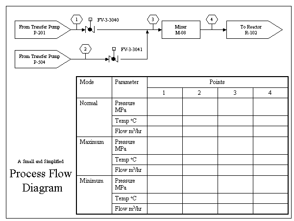
PFD’s show the relationships between the major components in the system. PFD’s also tabulate process design values for the components in different operating modes, typical minimum, normal and maximum. PFD’s do not show minor components, piping systems, piping ratings and designations.
A PFD should include:
- Process Piping
- Major equipment symbols, names and identification numbers
- Control, valves and valves that affect operation of the system
- Interconnection with other systems
- System ratings and operational values as minimum, normal and maximum flow, temperature and pressure
- Composition of fluids
This figure depicts a small and simplified PFD:
Related reading
Series: Piping Training Sections | Previous: Pipe & Fitting CAD Tools – Downloads | Next: P&ID’s