

Laser Scanning for Piping Designers: A Modern Methods Guide
Laser scanning records an existing plant as millions of measured points. For a piping designer, that point cloud is a measured picture of what is really there: the pipe, the steel, the valves, and the clutter that never made it onto the drawings. This article explains how scanning fits into modern piping design, when it pays, and how to use the data without trusting it blindly.
What laser scanning is
A scanner sends out laser pulses and measures the distance to every surface it hits. It sweeps across the space and records each hit as a point with a position, and often an intensity or colour value.
One setup gives one view. A full area needs many setups, joined together into one point cloud. The joined cloud is the deliverable you design against.
The cloud is not a model. It has no pipes, no line numbers, and no specs. It is a measured surface. Turning it into useful design information is the designer’s job.
Why piping teams use it
- Brownfield tie-ins. New lines must meet old lines at the right point, angle, and elevation. Scan data shows where the existing pipe really is.
- As-builts. Old drawings drift from reality. A scan records the plant as it stands today.
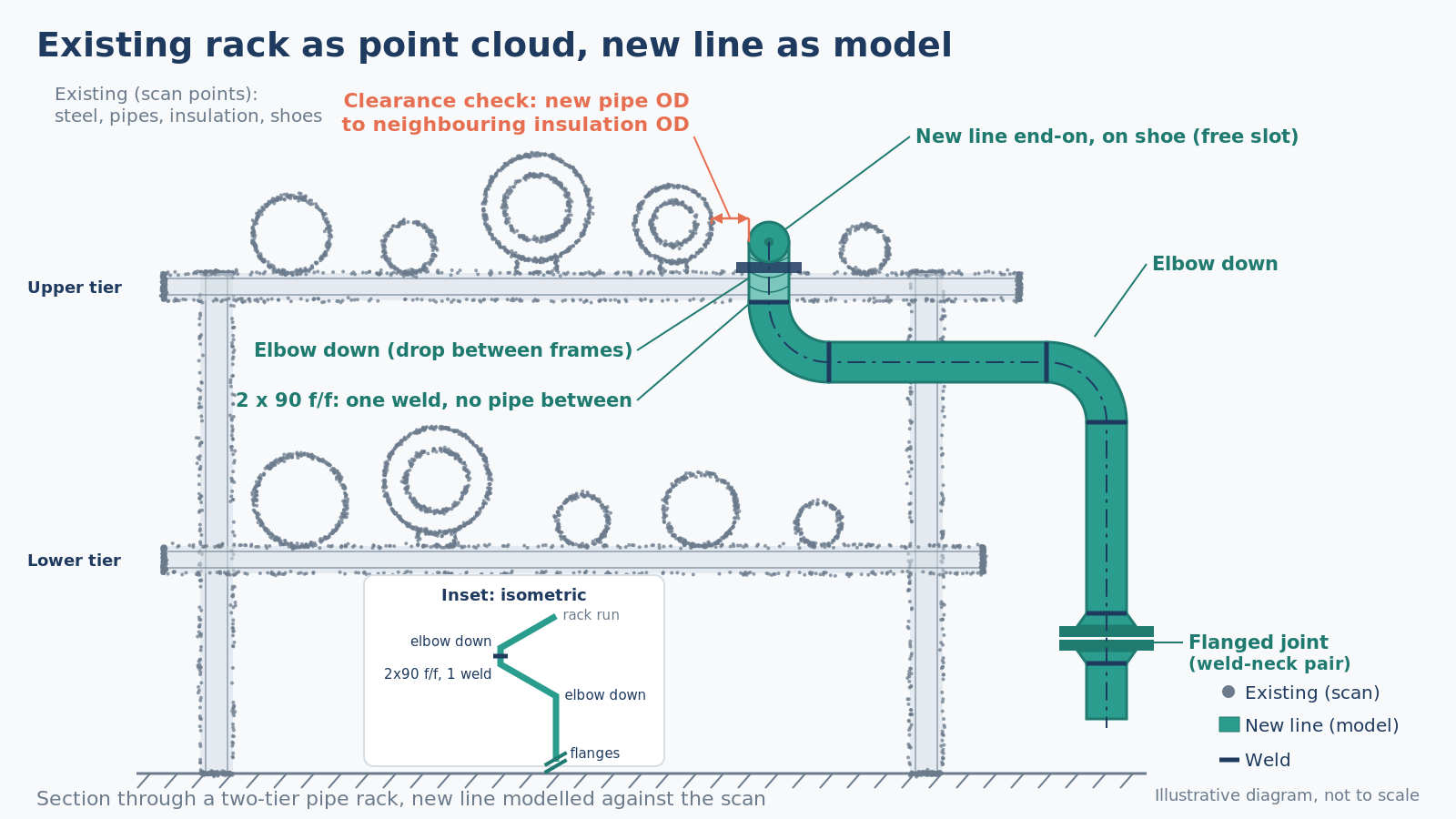
- Clash checks. New routing can be checked against the existing plant, not just against the parts somebody modelled.
- Shutdown planning. Work in a short outage window must fit first time. Scans let you plan spools, access, and lifting before the plant stops.
- Fewer site visits. The team can walk the cloud from the office, and so can people in other countries.
When it is worth it, and when it is not
Scanning is worth it when the existing plant is congested, the drawings are unreliable, the work has many tie-ins, or the outage window is short. It also helps when site access is difficult, hazardous, or expensive.
It may not be worth it for a single tie-in on an open pipe rack that a fitter can tape-measure in an hour. It adds little on a greenfield site with nothing there yet. It is also a poor fit when the area will change before the work starts, because the scan will be out of date.
Ask three questions. What will we decide from this data? How accurate does that decision need to be? Will the plant still look like this when we build? If the answers are vague, sort them out before you book a scanner.
Planning a scan
Good scan data starts with a scope, not a scanner. Agree what must be captured, to what level of detail, and why.
- Mark the area on a plot plan, including elevations and levels.
- List the items that matter most: tie-in points, nozzles, steel, supports, and access routes.
- Agree the deliverables: raw cloud, registered cloud, report, and any modelling.
- Agree the coordinate system. Plant grid, site grid, or a local system tied to known points.
- Plan permits, safety, hot surfaces, moving machinery, and who escorts the scan team.
Shadows are the common gap. A scanner cannot see behind a pipe or under insulation. More setups, from different angles, reduce shadows around the areas that matter.
Registration basics
Registration joins individual scans into one cloud. There are two main methods, and most jobs use a mix.
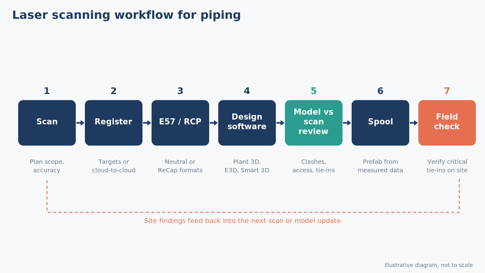
Target-based registration uses targets such as spheres or checkerboards placed in the scene. Each target must appear in more than one scan. Software matches them and locks the scans together. Surveyed targets also tie the cloud to the plant coordinate system.
Cloud-to-cloud registration matches the shapes in overlapping scans. It needs good overlap between neighbouring setups and enough distinct geometry. Long, plain corridors are harder to register than busy plant areas.
Ask for a registration report. It should show how well the scans fit together and how the cloud was tied to control. If nobody can explain the report, treat the data with care.

Point cloud formats
Scanner makers have their own native formats. For exchange, ask for a vendor-neutral format as well.
E57 is the common neutral format. Its specification is published as ASTM E2807. Most scanning and design software can read or write it, which makes it a sensible archive and handover format.
RCP and RCS are the Autodesk ReCap formats. An RCS file holds one scan. An RCP file is a project that references a set of RCS files. Autodesk design tools, including Plant 3D, attach clouds in this form.
Other formats such as LAS, PTS, and PTX also appear. Agree the format, units, and coordinate system in writing before the scan.
Using point clouds in design software
The main plant design tools all work with point clouds, in slightly different ways.
AutoCAD Plant 3D. The cloud is usually indexed in ReCap first, then attached to the drawing as an RCP or RCS file. Designers route pipe against the cloud, snap to points, and use cropping and sectioning to see one area at a time.
AVEVA E3D. Point clouds can be brought into the design environment and viewed alongside the model, for routing and clash work against the existing plant.
Smart 3D. Point cloud data can also be referenced with the model, so the design can be checked against existing conditions.
The details depend on the software version and add-ons. Check what your project licence and IT setup support before the scan is delivered. Large clouds may need local indexing and good graphics hardware.
Scan-to-model and model-vs-scan checking
These are two different tasks.
Scan-to-model means building intelligent objects from the cloud: pipe, fittings, valves, and steel. It is slow and costly, so model only what the project needs. Usually that is the lines you tie into, the steel you support from, and items you might clash with.
Model-vs-scan means overlaying your new design on the cloud and checking it. Look for clashes, access problems, and tie-in mismatches. Review it as a team, area by area, the same way you would run a model review.
Keep a clear line between measured and modelled. A modelled pipe is somebody’s interpretation of the points. Note who modelled it, from which scan, and on what date.
Measuring tie-ins and fabricating spools
Scan data lets you prefabricate spools that would once have been field-fit. That is a big gain, but only if the measurement is good.
- Measure the tie-in point from a clear part of the cloud, not a shadow or a noisy edge.
- Check the pipe centreline, the face of the flange, and the orientation of bolt holes where they matter.
- Check the existing pipe size and wall against the line list and site records. The cloud shows the outside surface only.
- Allow for insulation, cladding, and paint. The scanner sees the outside of whatever is there.
- Add field welds or adjustment where the risk is high, as your project practice requires.
Always field-verify critical tie-ins before cutting or welding. Plants move, supports get changed, and scans age. A quick site check is cheap compared with a spool that does not fit during a shutdown.

Accuracy
Do not assume a cloud is accurate enough just because it looks sharp. Accuracy depends on the scanner, the range, the surfaces, the registration, and the control survey.
The required accuracy comes from the project specification. The scanning provider should give an accuracy statement for the instrument and for the registered result. Compare the two before you design from the data.
If the spec is silent, raise it. Agree in writing what accuracy each use needs: a layout study needs less than a prefabricated tie-in spool.
Static, handheld, and drone scanning
Static terrestrial scanners sit on a tripod and scan from fixed setups. They suit detailed piping work where measurement quality matters most.
Handheld and SLAM scanners capture data while the operator walks. They are fast and good in tight spaces. Their results usually depend more on how the walk was done and on control points, so check the accuracy statement closely before using them for fabrication.
Drones capture roofs, tall structures, tank tops, and large sites. They help with overall layout and context. Close-in piping detail usually still needs ground-based scanning.
Many projects combine methods: static scans for tie-in areas, handheld for the gaps, drones for the overview.

Data handling
Point clouds are large. A full unit can run to hundreds of gigabytes of raw data. Plan storage, backup, and transfer before delivery, not after.
- Agree who stores the master data and who gets working copies.
- Split clouds by area so designers load only what they need.
- Keep the raw data, the registered cloud, and the report together.
- Record the scan date in file names and metadata.
Treat scan data as client-confidential. A cloud shows the plant in detail, including security features and layout. Follow the client’s rules for sharing, cloud storage, and deletion at project close. Do not post screenshots publicly without permission.
Practical checklist
- Write down what decisions the scan must support.
- Get the required accuracy from the project spec, or agree it in writing.
- Mark the scan area, levels, and priority items on a plot plan.
- Agree the coordinate system and control points.
- Agree deliverables: formats (E57 plus any native or RCP/RCS), units, and report.
- Plan permits, access, safety, and escort.
- Choose static, handheld, drone, or a mix, based on the accuracy needed.
- Check the registration report and the accuracy statement on delivery.
- Confirm the cloud loads in your design software at a workable speed.
- Model only what the project needs, and record who modelled it and from which scan.
- Run model-vs-scan reviews area by area.
- Field-verify critical tie-ins before fabrication.
- Store and share the data under the client’s confidentiality rules.
How it fits with PipingDesigners tools
Our tools do not process point clouds. They help with the checks around them.
When you measure a tie-in from a scan, the cut-length and pipe-offset tools give a quick way to cross-check spool dimensions before they go on an isometric. They are a check, not a replacement for your design software or the fabricator’s review.
Iso Tracker, currently in beta, is being built to track isometric status, including as-built updates. Scan-based as-builts are one source of that information.
Laser scanning is now part of normal brownfield work. Used with a clear scope, a stated accuracy, and field checks on critical points, it turns guesswork into measurement.