It Looks Complete. Is It Ready? Rethinking How Piping Isometrics Are Released
By Anton Dooley, SPED PPD Level IV, PipingDesigners.com
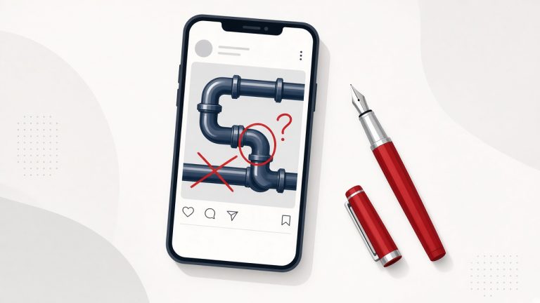
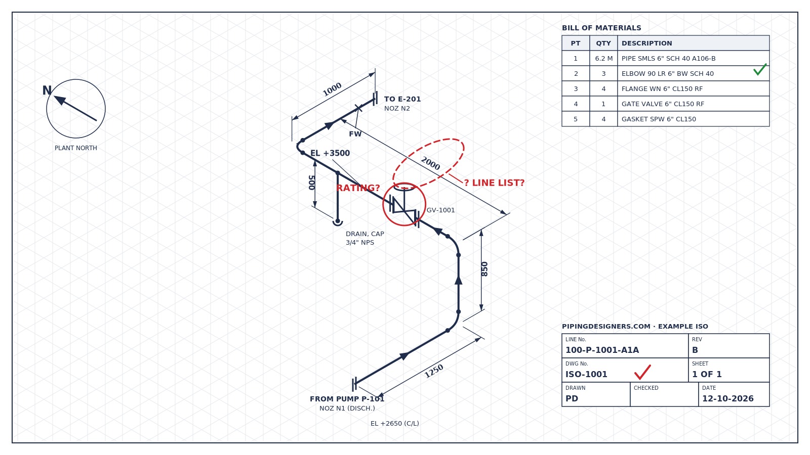
Every piping designer has seen it. The isometric is clean. The dimensions line up, the title block is filled in, the BOM sits neatly in the corner, and the checker’s initials are on it. It goes out.
Then the questions start. The line size doesn’t match the line list. A valve is shown at a rating the class doesn’t allow. The P&ID was revised a fortnight ago and nobody carried the change across. The fabricator wants to know which welds are field welds.
None of this was hidden. It just wasn’t checked.
That is the argument of this article, and of the checklist that goes with it:
A piping isometric can look complete, pass a quick visual review, and still not be ready for release.
This isn’t another guide to drawing checking. Most of us know how to check a drawing. What follows is a set of proposed themes about why checking so often misses things, and what changes when release becomes a gate rather than a glance. I’m putting these forward to test against your experience, not as a claim that every project fails the same way.
If you want something practical to use alongside this article, the free Isometric Release Gate Checklist turns these ideas into a printable, fill-in check you can apply to your own drawings.
Why it matters
An isometric is rarely the end of the line. It feeds the material take-off, procurement, spool fabrication, the test pack and site erection. An error that survives release doesn’t stay on the drawing. It turns into material ordered to the wrong specification, a spool that doesn’t fit, a weld cut out and remade, or an RFI that holds up a crew.
The later an error is found, the more people and documents it touches, and the more it costs to undo. The cheapest place to catch a problem is before the drawing leaves the office.
Theme 1: Why checks fail
When an error gets through, the instinct is to blame the checker. In my experience, the cause is more often the conditions the check was carried out under. Five patterns come up repeatedly.
Checking against outdated inputs. A check is only as good as the documents it is checked against. If the checker is working from a superseded P&ID, an old line list or a model that has since moved on, the drawing can pass every check and still be wrong. The check confirms agreement with the wrong source.
Relying on visual completeness. A drawing that looks finished invites a reviewer to confirm what is there rather than question it. Missing information is much harder to spot than wrong information, because there is nothing on the sheet to catch the eye.
Inconsistent checking methods. Two checkers given the same isometric will often check different things in a different order, to a different depth. Without a common method, the quality of the check depends on who did it and how busy they were that day.
Late changes. The drawing was checked on Tuesday. A change came in on Thursday. The revision went out on Friday. Was the change checked, or only drafted? Changes made after the check are one of the easiest ways for errors to slip into a release that is officially “checked”.
Unclear release responsibilities. Who decides the drawing is ready? The designer who produced it, the checker who marked it up, or the lead who signs the title block? When nobody is clearly accountable for the release decision, it tends to happen by default rather than by judgement. Self-checking under schedule pressure is a symptom of the same problem.
Theme 2: The comments that keep coming back
Look at the checking comments on almost any project and the same categories turn up again and again:
- Missing or conflicting dimensions. An offset with no dimension, or two dimension strings that don’t add up.
- Incorrect or incomplete component information. The wrong rating, the wrong facing, or a fitting described too loosely to buy.
- Discrepancies against the P&ID or line list. A missing vent, a valve in the wrong place, a size or class that disagrees with the line list.
- Unresolved revisions. Clouds without explanation, changes noted but not carried through, or a revision raised against an input nobody has confirmed.
- Unclear fabrication details. Shop and field welds not distinguished, spool breaks missing, or special requirements buried in notes.
- Incomplete material information. BOM entries that don’t match the drawing, missing gaskets and bolting, or vendor and free-issue items not identified.
The comments themselves are rarely the problem. How they are handled is. “Check this” tells the designer nothing. Comments get closed without anyone verifying the fix. A comment raised on revision A is lost by revision C. A correction is made on the iso but never reaches the MTO or the adjoining isometrics. And when the back-check covers only the clouded areas, any knock-on effect elsewhere on the drawing goes unseen.
If the same comment appears on drawing after drawing, it isn’t a one-off error. It is a gap in the process.
How many of these show up on your own drawings? Try running a recent isometric through the Isometric Release Gate Checklist and see which gates it would struggle with.
Theme 3: Why appearance is deceptive
Good drafting deserves credit, but neatness tells you about presentation. It tells you nothing about verification.
A clean drawing is not proof that:
- its design basis (line number, size, class, service and design conditions) agrees with the approved line list and P&ID;
- its interfaces (nozzles, tie-ins, branches and continuations) match the equipment and the adjoining lines;
- its access and constructability work in practice: the tube bundle can still be pulled, the pump lifting beam is clear, valves can be reached, and the spools can be fitted and welded;
- its materials are correct for the class and service;
- its quantities in the BOM match what is actually drawn;
- its revision status, and the status of everything it depends on, is current and approved.
An isometric can be perfectly consistent with itself and still reflect an outdated or conflicting design. That is the trap. A visual review checks the drawing against the drawing. A release check has to check the drawing against the evidence.
Theme 4: What a release gate changes
If those themes ring true, the answer is not to check harder. It is to check differently: to move from an informal visual inspection to a repeatable, evidence-based process with explicit outcomes and recorded responsibility.
That is what the Isometric Release Gate Checklist sets out to do. It is a printable, manual checklist that takes an isometric through eight gates before release.
The guiding principle is simple:
An isometric should not be released simply because the drawing looks complete. It should be released only when the required checks have been completed, discrepancies have been resolved or formally dispositioned, and the release has been authorised.
The eight gates in brief
- Gate 0: Document and release identification. Confirm what the drawing is, which revision it is, what it is being released for, and which inputs govern it. If the revision or design basis can’t be confirmed, stop there.
- Gate 1: Design basis and line information. Line number, size, class, service, design conditions and special requirements agree with approved information. Conflicts are escalated, not guessed at.
- Gate 2: Routing, geometry and interfaces. Dimensions, orientation (including a north arrow that points to project north and agrees with the rest of the set), nozzles, tie-ins, slopes, vents, drains and supports, checked against the approved model or arrangement, plus specific access and constructability checks such as valve operation, tube bundle pull space, pump lifting beam clearance, headroom and installation.
- Gate 3: Components, materials and BOM. Component specification, ratings, valves, gaskets, bolting, welds and the material take-off, judged against the stated release purpose. A design-review iso is not automatically a fabrication MTO.
- Gate 4: Drawing presentation and fabrication information. Legibility at the issued size, clear dimensions, weld and spool information, notes, the title block, and a complete issued PDF with no superseded content.
- Gate 5: Cross-document consistency and revision control. The isometric agrees with the P&ID, the line list and the model, and the governing revisions are current.
- Gate 6: Technical review and outstanding actions. Checker and specialist reviews are complete, comments are closed or dispositioned, and changes after the check have been reassessed.
- Gate 7: Final release authorisation. Mandatory gates are complete, exceptions are approved, the correct status and revision are assigned, and the right controlled document goes to the right people.
Explicit outcomes, not ticks
Each check is recorded with one of four outcomes:
- PASS: the requirement is satisfied and evidence is available.
- FAIL: the requirement is not satisfied and a correction is required.
- N/A: not applicable, with the reason recorded.
- HOLD: it can’t be verified yet, information is awaited, or an authorised decision is needed.
HOLD matters more than it might seem. It gives the checker an honest answer when the evidence isn’t there, instead of a choice between a hopeful tick and an awkward conversation.
A critical failure or unresolved hold that affects the intended release stops the release until it is resolved or formally dispositioned. Where the project procedure allows it, a drawing can be released with authorised exceptions, but only if those exceptions are documented and approved and no mandatory requirement is broken. A recorded exception is not automatically permission to release.
The checklist ends with a Release Decision Record: Release, Release with authorised exceptions, Hold or Reject, signed by the checker and the authorised approver. Responsibility is written down rather than assumed.
Cross-document consistency: where clean drawings fall down
If I had to pick one gate that clean drawings most often fail, it would be Gate 5.
The P&ID, the line list and the model are produced by different people, at different times, often in different tools. Each can be right on its own terms and still disagree with the others. The isometric sits in the middle and has to be consistent with all three.
In practice, that means checking:
- against the P&ID: line identity, branches, valves, flow direction and process connections, allowing for the way each discipline represents things;
- against the line list: line number, size, specification, service and design conditions;
- against the model: that the isometric matches the authorised model or approved geometric source;
- revision currency: that each governing document is at an approved, current-for-purpose revision. The newest revision number isn’t automatically the technically correct one.
When something doesn’t agree, the discrepancy is recorded, assigned and resolved, or formally dispositioned. It isn’t quietly fixed on the iso and forgotten. And the downstream impact on associated isos, MTOs, supports and stress gets considered before release.
What the checklist is not
To be clear about the limits: the checklist doesn’t replace project procedures, approved design documents, codes or engineering authority. It is not a design calculation. It doesn’t verify stress, flexibility, hydraulics, support loads or pressure integrity. Project requirements always take precedence, and each project decides which checks are mandatory for each release stage.
It is a structured way of asking, before release, “How do we know?” rather than “Does it look right?”
Do these patterns match your experience?
This is version 0.1, a practitioner review draft. It hasn’t been validated for project use, and it will only improve with input from people who check and release isometrics for a living.
I’d value your view on a few questions:
- Do these four themes match what you see on your projects, or are the real causes elsewhere?
- Which checks are missing from the checklist?
- Which should be mandatory, and which should depend on the project?
- What evidence can you actually produce from your CAD, PDM and document-control workflows?
- Who checks, who resolves and who authorises where you work?
More design checklists: browse the Design Checklists.
Share your recurring comments. I’m also collecting anonymised examples of the checking comments you see again and again, for a follow-up article. Please leave out any client, project or drawing details. Just the comment, and if you can, why you think it keeps coming back. Share them in the comments below.
Download the checklist and try it on your next release: open the Isometric Release Gate Checklist, work through the checks and download your completed PDF.
A clean isometric is a good start. A released one should be a checked one.