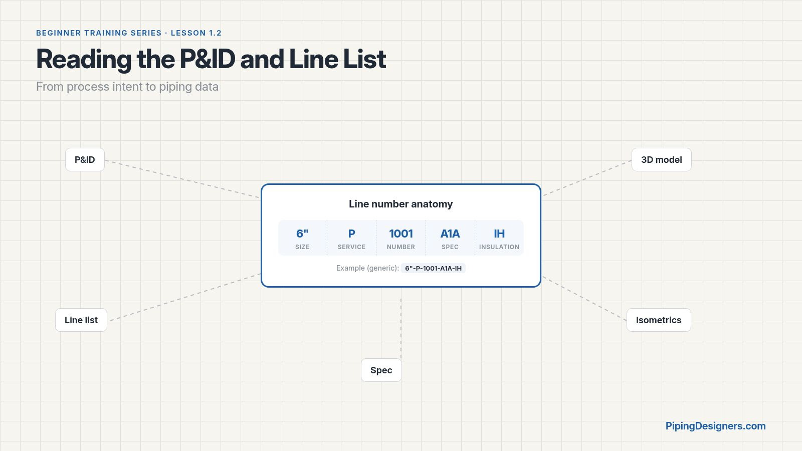
Lesson 1.2: From Process to Piping — Reading the P&ID and Line List
PipingDesigners Beginner Training Series · Module 1 · Lesson 1.2
What you will learn
By the end of this lesson you should be able to:
- explain what a P&ID shows, and what it deliberately does not show;
- read a line number and the main columns of a line list, and say what each one means for the piping model;
- spot the common mismatches between a P&ID, a line list and the early model;
- use a structured checklist when you review a P&ID so that process intent reaches the layout.
1. Why this lesson sits here
In Lesson 1.1 we said that process engineers own the P&ID and the line list, and that piping turns those into a buildable route. This lesson is about reading those two documents properly. If you misread them, every later deliverable — the model, the isos, the BOM — will be wrong in the same way.
You are not rewriting the process design. You are making sure you understand it well enough to place real components in real space.
2. What a P&ID is (and is not)
A Piping and Instrumentation Diagram (P&ID) is a schematic of a process system. It shows the equipment, the lines that connect them, the main valves, and the instruments that measure or control the process. It uses standard symbols and line conventions so that process, piping, instrumentation and operations can all read the same sheet.
A P&ID is not a scale drawing. It does not fix north, does not fix exact elevations, and does not tell you which side of a pump the suction pipe leaves on. Up and down on the sheet are only a rough hint. What it does fix is connectivity and intent: what must be connected to what, which valves and instruments sit on which lines, and which notes apply to which services.
That distinction matters. Your job is to convert the schematic into a layout that can be built, operated and maintained — without losing the process intent that the P&ID recorded.
| On the P&ID | What it usually means for piping |
|---|---|
| Equipment tag (for example P-210A) | The piece of equipment your nozzles and tie-ins must match |
| Line number | The identity of that pipe run in the line list, the model and the iso |
| Valve or specialty symbol | A component that must appear in the model and on the BOM |
| Instrument bubble | A connection, stand, or access point the layout must allow for |
| Note or call-out | A process rule (slope, no pockets, steam tracing, and so on) that the route must respect |
| Battery limit or tie-in mark | Where your scope starts or joins existing plant |
For a longer look at what to ask in a P&ID review, see the older PipingDesigners note Piping Guidelines for P&ID Review. The ideas in this lesson are consistent with that article, written for the beginner series.
3. Reading a line number
Every line on a process plant has a unique line number. The exact format varies by company, but most numbers pack the same kinds of information: size, a commodity or service code, a sequential number, and a piping class or spec reference. A made-up training example might look like this:
80-CW-1204-A1
One common reading of a string like that is:
- 80 — nominal size (here, DN 80 / NPS 3);
- CW — commodity or service (cooling water in this invented example);
- 1204 — the unique line sequence for that service;
- A1 — the piping class or specification that governs materials and rating.
Do not treat that breakdown as universal. Some owners put the class first, some include the unit number, some separate insulation and tracing into their own fields. The rule is simple: learn the project’s line-number convention before you model a single line, and keep it consistent across the P&ID, the line list and the model. The older PipingDesigners article Introduction to Line Numbering expands on why that consistency matters.
4. The line list
The line list (sometimes called a line designation table) is the tabular companion to the P&ID. Where the P&ID shows connectivity, the line list holds the data for each line. Typical columns include:
| Column | What the designer uses it for |
|---|---|
| Line number | The unique identity used in the model and on isos |
| From / To | Equipment or line ends that must match the P&ID |
| Size | The nominal size to model (NPS or DN) |
| Piping class / spec | Which component catalogue the software may offer |
| Design / operating pressure and temperature | Rating checks, stress flags, and insulation or tracing clues |
| Fluid / phase | Service behaviour (liquid, vapour, two-phase, slurry) |
| Insulation / tracing / painting | Outside diameter for spacing, and heat-tracing routes |
| Test medium and pressure | Test blinds, vents and drains the layout must allow |
| PWHT, NDE, or special notes | Fabrication and examination rules that affect spool breaks |
Not every project uses every column, and names differ. What matters is that the line list is the data source the model should follow. If the P&ID and the line list disagree, stop and raise a query. Do not silently pick one.
5. From process sheet to piping model
A practical sequence for a new designer looks like this:
- Open the P&ID for the system you are working on, at the revision the project has released for design.
- Find each line on that sheet in the line list. Confirm size, class, from/to and notes.
- Assign the matching piping specification in the 3D software so the component catalogue is correct.
- Route the line between the real nozzles, respecting process notes (slope, no pockets, minimum distances to instruments, and so on).
- Place the valves and in-line instruments the P&ID shows, with room to operate and maintain them.
- Record assumptions and queries. Do not invent data the documents do not give you.
Modern plant-design systems can hold a P&ID database and push line data into the 3D model. That helps, but it does not remove the need to read. A wrong class in the database becomes a wrong class in every iso.
6. Common mismatches to catch early
These are the disagreements that most often waste time later:
- Size or class on the P&ID does not match the line list. Resolve it before modelling.
- From/To on the list does not match the sheet. Someone may have revised one document and not the other.
- A valve or instrument is on the P&ID but missing from the model, or the other way round.
- A process note (fall, no pockets, steam jacket, heat tracing) never made it into the route.
- Tie-in numbers differ between the P&ID, the tie-in list and the existing drawings.
- Insulation thickness was ignored when spacing lines on a rack, so the outside diameters clash.
Finding any of these at the 30% model review is cheap. Finding them on an iso that has already gone to the shop is expensive.
7. Worked example: checklists that depend on the P&ID and line list
Try it: open the Design Checklists tool. It holds six lists for a piping job. For this lesson, focus on two of them:
- Under Piping general arrangement, tick through the item that says line numbers, sizes and classes can be read and match the line list. That is exactly the P&ID-to-list-to-drawing consistency this lesson is about.
- Under Tie-ins, read the items about unique tie-in numbers, host line identity, isolation and pressure-test separation. Those only make sense if you have read the P&ID and the tie-in marks correctly.
You do not need a live project drawing to do this. Read each item and ask yourself: “Which process document would I use to answer that?” The companion article Design Checklists — Companion Article explains how the tool is meant to be used. Later lessons return to the plot-plan, equipment, iso and MTO lists.
Summary
- A P&ID records process connectivity and intent; it is not a scale layout.
- The line list holds the data for each line; the model should follow it.
- Line-number formats vary — learn the project convention and keep it consistent.
- When documents disagree, raise a query. Do not invent the missing answer.
- Checklist items on general arrangements and tie-ins are a practical way to confirm that process data reached the design.
Quick quiz
- A P&ID primarily shows:
a) Exact coordinates and elevations b) Process connectivity, valves and instruments c) Fabrication weld maps - Who normally owns the P&ID and line list?
a) The fabricator b) The process engineer c) The stress engineer - The line list and the P&ID disagree on line size. What should you do?
a) Model the larger size to be safe b) Raise a query and wait for an answer c) Leave the size blank in the model - In the invented line number 80-CW-1204-A1, the “A1” part most often stands for:
a) The plot area b) The piping class or specification c) The welder stamp - Which Design Checklists section explicitly asks whether line numbers, sizes and classes match the line list?
a) Material take-off b) Piping general arrangement c) Plot plan - A process note on the P&ID says the line must drain with no pockets. Where should that show up?
a) Only in a meeting note b) In the routed line and its low-point drain c) Only on the insulation schedule
Answers: 1 b, 2 b, 3 b, 4 b, 5 b, 6 b.
Next lesson
Lesson 1.3 — Codes you’ll meet, and what a designer actually needs from them.
Tell us what you think. This is part of the beginner training series and we want your feedback. Was it the right level? Too long, too short, anything missing or wrong? Leave a comment below.